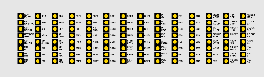
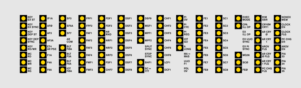
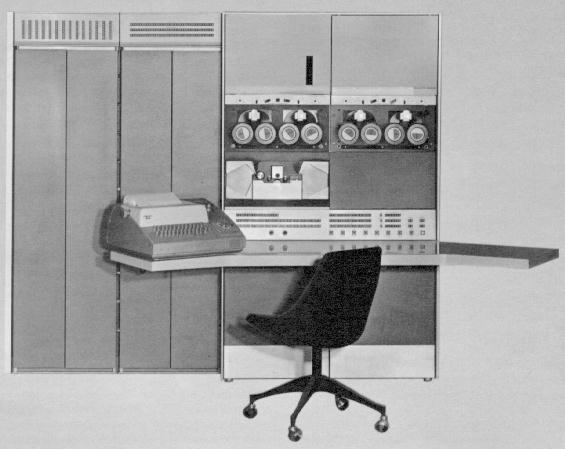
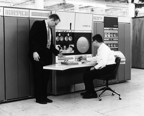
Some photos of the PDP-6 show a reduced set of lamps in indicator panel in bay1 (the leftmost). The full grid can be seen in this photo. The reduced grid can be seen here for instance.
For a comparison of the flip-flops displayed on that panel, see my artwork:
The AR COM CONT flip-flop. It is set when AR is to be complemented after an addition
The MC SPLIT CYC SYNC flip-flop. From the instruction manual (3-12):
Indicates that if there was a read-pause-write call during the preceding fetch cycle, it triggered only a read request, and the subsequent restart triggered a separate write cycle.
This flip-flop is used to break a read-pause-write memory cycle in two. It is set whenever a memory stop can happen (i.e. KEY MEM STOP is down or SW ADDR STOP is on. Also if MC DR SPLIT is asserted, which comes from a drum so it can have access to the memory while the APR is executing.
The MC STOP SYNC flip-flop. From the instruction manual (3-12):
Indicates that the preceding fetch cycle triggered a read-pause-write memory cycle.
This flag is used to manually restart the write of a read-pause-write cycle, but I don't quite understand under which conditions this can even happen.
From the instruction manual (3-13):
Indicates that the number displayed by the MEMORY ADDRESS lights is identical to that contained in the ADDRESS switches. This light is on whenever an address stop occurs but may be on at other times as well.
This flip-flop is checked after every memory access. If it is set, the word read or written will be displayed on the memory indicator lights (MI). In addition, if it is set and the address stop switch is on, the machine will stop after a memory access.
The subroutine flip-flop of UUO instructions.
The CPA PDL OV flip-flop. Set when an overflow in one of the stack instructions (PUSH, PUSHJ, POP, POPJ) occurs.
From the instruction manual (3-11):
[This] flip-flop inhibits relocation when a UUO or an illegal user instruction is trapped, and the light is always off at an instruction stop.
Set after the instruction cycle to inhibit generating the EX IR UUO level when IR has been cleared. It's not quite clear to me why generating EX IR UUO would be so harmful.
Set whenever PI CYC is set (after a PI cycle has been entered). Used to inhibit relocation in the store cycle since PI CYC is cleared before the store cycle. I don't understand the intricacies here, why can't PI CYC be reset later, i.e. at ST7?